

Mounting, Turning On & Configuring Device
-
https://player.vimeo.com/video/877660695 Mount sensor where applicable close to a power outlet (as this is powered by a 12V power adapter that will be provided) https://player.vimeo.com/video/877661991
-
This is a WiFi Enabled device. After mounting, get off the current WiFi network, go onto the People Counter’s WiFi (SSID People Counter_XXXXXX. EX: People Counter_F7D7D2)(This is printed on the bottom side of the device)
-
Accessing the Sensor: Web GUI https://player.vimeo.com/video/877665781
-
Once the LED light is BLUE, go to step B
-
On your Web Browser, login to 192.168.1.1
-
Set your Password and the Security Questions of your choice.
-
To change The Password and Security Questions, please navigate to the SYSTEM tab.
USERS MODIFY: Resets Password SECURITY QUESTIONS: Reset Security Questions.
-
-
Environment Requirements:
-
Dark floor/carpet (black, grey, etc.) will affect the device to count staff when Staff Detection is enabled.
-
Avoid 940nm light which may result in incorrect counting
-
Outdoor sunlight shining on the over channel will not have any effect, but the mirrored reflections that allow sunlight on the ToF Sensor should be avoided.
-
When the carpet/floor is black, make sure there are no obstacles within a 60 cm hemisphere range in the direction of the device. Otherwise, the device imaging may appear abnormally red.
-
-
Factors Affecting Accuracy
-
Wearing a fisherman’s hat or carrying a cardboard box on the shoulder. The target will not be recognized because it will become unlike a human depth map.
-
Handheld or cart carrying a humanoid doll with sufficient height to pass by: The doll will be mistakenly detected as people because it is human-like in depth map.
-
-
INSTALLATION
-
Ensure that thickness of the ceiling is more than 30mm, then attach the mounting sticker to the ceiling and drill 4 holes with a diameter of 6mm. If the wire needs to be extended to the interior of the ceiling, a wire hole with a suitable size is also required to be drilled.
-
Fix the wall plugs into the ceiling holes.
-
Remove the cover on the device, and then connect all required wires and pass them through the wire hole behind the device or block on the side of the device if the wires need to be protruded from the side to the device.
-
Fix the device to the to the wall plugs via mounting screws: remember to adjust the mounting direction according to the detection area requirement.
-
Fix the cover back to the device.
-
-
For the Installation Height, navigate to the RULES tab under Deployment Parameters, set the correct height, measure with a measuring stick, and set that in Millimeter
-
Once the height is accurate, the Counter is ready to use.
-
COVERED DETECTION AREA
-
The detection area covered by the device is related to the field of view angle of the device, the installation height and the target height. The length of the detection area is approximately x=2.300×(H-hmin) and the width of the detection area is approximately y=1.678 x (H-hmin).
-
-
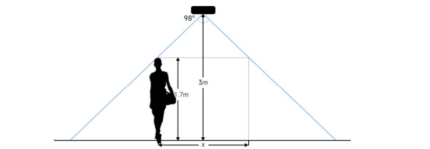
Example: If the Minimum height of the pedestrian is 1.7 m, the detection area corresponding to each installation height is as follows: 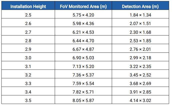
-
Enabling Dwell Detection
STEP 1
Connect to the VS133 Local Wi-Fi. (Remember to be off local Wi-Fi to be able to connect to the devices Wi-Fi)
STEP 2
Navigate to Rules (Second tab when you log-in to Web UI)
STEP 3
On the Right side of the screen, you will see where it says Counting Strategy. Underneath that you will see where it says Region Monitoring, Please turn that on.
STEP 4
After turning on Region Monitoring, Navigate back to the image of the device, and draw the lines where you would like to detect. Then Click the blue check mark in the dialogue box to save the changes you made.
STEP 5
The Advanced Properties dialog will pop up after saving. In the Advanced Properties dialog box is where you can enable the Dwell Time Detection. Click on blue check mark in dialogue box to save the changes that you have just set. Save again and you’re done.